 English
 русский
 عربى
عربى Español
Qinlang focuses on providing high-quality products and considerate services, and is committed to meeting every expectation of our customers.
The DKT-133 Cooling Ventilation Double Inlet Air Conditioning Fan is d...
See Details
Stand near a running fan and you hear it right away. Air moving at speed creates turbulence. Turbulence produces pressure changes. Those pressure changes reach your ears as sound. The blades push air, and that pushing creates noise across a range of frequencies.
Blade rotation causes a primary source of sound. Each blade shoves air forward while creating lower pressure behind it. The pressure difference changes as blades pass any fixed point. That fluctuation produces a tone at the blade passing frequency. Higher harmonics follow.
Vortices form at blade tips. High-pressure air from one side meets low-pressure air from the other. Those tip vortices trail behind and generate broadband noise. The trailing edge of each blade creates its own vortices as air separates. That wake turbulence adds to the sound signature.
Motors make their own noise. Bearings produce mechanical noise through rolling contact. Electromagnetic forces between stator and rotor create vibrations that radiate as sound. Switching electronics in brushless designs add high-frequency whine.
The housing transmits vibrations from both motor and airflow. A housing that resonates at certain frequencies amplifies those sounds. The interaction between spinning blades and stationary housing creates additional pressure variations.
Some observations about fan noise sources:
Blade geometry shapes the airflow and determines how turbulence develops. Small changes in blade shape can affect sound levels noticeably.
Blade angle changes how air enters and leaves. A steeper angle moves more air per revolution but creates greater pressure differences. Those differences generate stronger sound. A shallower angle reduces pressure difference but requires higher speed for the same airflow.
Chord length, the blade width from leading edge to trailing edge, influences pressure distribution along the blade. Longer chords spread the pressure change over a greater distance. That spread reduces local pressure gradients and the sound they produce.
Blade curvature affects air separation from the surface. A blade that curves too sharply causes early separation. Early separation creates turbulence and noise. A smoother curve keeps air attached longer, reducing the turbulent wake.
Surface roughness adds friction noise. Air over rough surfaces creates small eddies near the blade. Those eddies add broadband noise across a wide frequency range. Smoother surfaces reduce this source.
Several design strategies address aerodynamic noise directly. Each targets a specific mechanism of sound generation.
Blade sweep changes how each section of the blade meets incoming air. Swept blades reduce the pressure difference at any single radial position. That reduction spreads loading over a larger area and lowers sound intensity.
Tip clearance between blade and housing affects vortex formation. A larger gap allows stronger tip vortices and more noise. A tighter gap reduces bypass flow that causes vortex formation. The practical limit comes from thermal expansion during operation.
Blade spacing optimization reduces interaction noise between adjacent blades. Uneven spacing prevents tonal energy from building up at a single frequency. Energy spreads across a broader range, reducing the peak level at any one frequency.
Leading edge modifications soften air entry into the blade passage. A rounded leading edge lets air accelerate gradually. A sharp leading edge creates immediate pressure changes. Gradual acceleration reduces the pressure pulse and associated sound.
| Design Feature | How It Reduces Noise | What It Does In Practice |
|---|---|---|
| Blade Sweep | Reduces Pressure Differences | Lowers Blade Passing Tone |
| Tight Tip Clearance | Reduces Bypass Flow | Reduces Vortex Noise |
| Uneven Blade Spacing | Spreads Tonal Energy | Lowers Peak Sound Levels |
| Rounded Leading Edge | Provides Gradual Air Acceleration | Reduces Pressure Pulses |
Speed drives much of the noise in axial fans. Sound levels rise with blade tip speed. Higher speeds create higher pressure differences and more turbulence. Lower speeds reduce both.
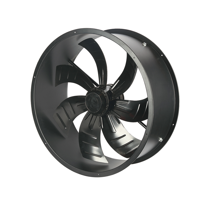
Airflow needs conflict with speed limits. You must move a certain amount of air to cool or ventilate. You can move that air with a large fan at low speed or a small fan at high speed. The low-speed approach usually produces less noise.
Multi-speed operation lets the fan run slower when less airflow is needed. That flexibility reduces noise during low-demand periods. The noise profile changes with speed, often shifting from tonal to broadband as speed drops.
Electronic speed control manages noise across operating conditions. Variable speed drives allow gradual acceleration and deceleration. Gradual changes avoid the abrupt pressure changes that create noise. The control system adjusts speed based on actual needs rather than worst-case assumptions.
Motor design affects fan noise through several pathways. Bearing selection influences mechanical noise. Electromagnetic design affects vibration and audible hum.
Bearing types differ in noise characteristics. Ball bearings make some rolling element noise but last longer. Sleeve bearings run more quietly but may have shorter life. The choice balances noise against reliability requirements.
Electromagnetic noise comes from switching transitions in brushless designs. Fast switching generates high-frequency components that can be objectionable. Slower switching reduces these frequencies but affects efficiency. Control algorithms can shape switching to reduce audible noise.
Motor mounting isolation prevents vibrations from reaching the housing. Isolators at mounting points absorb vibrational energy before it transmits. The housing then does not become a secondary sound source.
Cooling airflow within the motor adds noise. Air passing through motor openings creates turbulence. Designs that minimize internal airflow restrictions reduce this source.
The housing surrounds the blades and directs airflow. It also radiates sound unless designed not to. Housing shape and thickness both play a part in how much noise gets out.
Inlet geometry affects noise before air even reaches the blades. A sharp-edged inlet creates turbulence at the entry point. That turbulence generates noise that adds to everything else. A rounded inlet allows smooth entry and reduces that source.
Outlet geometry matters too. The way air exits affects how much turbulence occurs at discharge. Turbulence at the outlet radiates sound outward. Smooth transitions reduce that turbulence.
Housing thickness influences how much vibration gets transmitted. Thin housings flex and vibrate more readily. They radiate more sound as a result. Thicker housings provide more mass and resist vibration. They weigh more and cost more too.
Acoustic absorption materials inside the housing absorb sound energy. Foam linings or fibrous materials convert sound energy to heat through friction. They work across many frequencies but add complexity to manufacturing.
Sound does not radiate equally in all directions. Housing shape can direct sound away from occupied areas. That reduces perceived noise even if total output stays the same.
Points about housing design:
Materials affect both sound generation and transmission. Some absorb sound. Others damp vibration. The choice shapes the noise outcome.
Damping properties determine how fast vibrations decay. Materials with high internal damping convert vibration energy to heat. That conversion reduces the energy available to radiate as sound. Metals have low damping. Polymers and composites offer more.
Porous materials absorb sound waves through friction. Non-porous materials reflect sound. A housing made of absorbing material reduces reflected noise. Structural needs often require a mix of materials.
Stiffness influences vibration amplitude. A stiffer structure deflects less under load. Less deflection means less surface movement to radiate sound. The trade-off is that stiffer materials tend to have lower damping.
Dense materials transmit less sound because they have higher mass. The same force produces less acceleration in a dense material. Less acceleration means less sound radiation.
A fan that runs quiet in one condition may sound different in another. Pressure, temperature, and installation all change the noise profile.
Pressure load variations change the operating point on the fan curve. High resistance means less airflow but different pressure fluctuations. Low resistance allows more airflow but changes the noise spectrum. The fan sounds different across its operating range.
Temperature affects air density. Denser air carries more energy and can create more noise. Changes in air density affect aerodynamic loading and acoustic transmission.
Installation constraints matter. A fan near a wall reflects sound differently than one in open space. Obstructions create turbulence that adds noise. The same fan in two different locations sounds like two different products.
Age-related changes happen gradually. Bearings wear and add mechanical noise. Dirt on blades changes airflow and increases turbulence. Vibration damping materials degrade and lose effectiveness over time.
A few things that change fan noise over time:
Installation affects how much noise the fan makes and how much reaches the listener. Good practices reduce sound at the source and prevent transmission.
Vibration isolation prevents mechanical noise from traveling through building structures. Isolators absorb vibrational energy before it reaches the structure. That energy then does not radiate from walls or floors.
Duct connections affect how sound travels through the system. Flexible connections at duct interfaces reduce sound transmission. Rigid connections transmit sound efficiently. Proper duct sizing keeps airflow velocity at design conditions. Higher velocities create additional noise from duct turbulence.
Inlet and outlet clearance matters for aerodynamic performance. Restricted inlets create turbulence before air reaches the blades. That turbulence adds noise. Outlet restrictions create back-pressure and change operating conditions.
Orientation affects sound emission direction. A fan that aims sound toward occupied areas creates greater annoyance. Orienting the discharge away from sensitive areas reduces perceived noise.
There is only so quiet an axial fan can get. Physics, cost, and performance all set boundaries.
Moving air makes noise. That is the starting point. A fan that moves no air makes no noise. Every increase in airflow comes with some increase in sound. The relationship is fundamental.
Cost affects noise reduction. Acoustic materials, complex blade shapes, and precision manufacturing add expense. The added cost may not make sense for applications with modest noise requirements.
Performance trade-offs happen with lower noise. A quieter fan may have lower efficiency or reduced pressure capability. The designer balances noise against other performance parameters.
Noise requirements vary by application. An office environment expects quieter operation than a factory floor. What works in one place may be unacceptable in another. Design choices reflect these differing needs.
A Low Noise Axial Fan represents a balance of aerodynamic design, material selection, and installation practices to achieve acceptable noise levels without compromising performance.
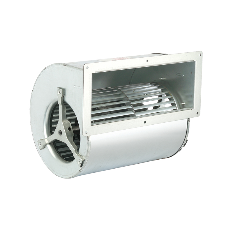
The DKT-133 Cooling Ventilation Double Inlet Air Conditioning Fan is d...
See Details
The DKT-146 Multi-Function Variable Frequency Double Inlet Air Conditi...
See Details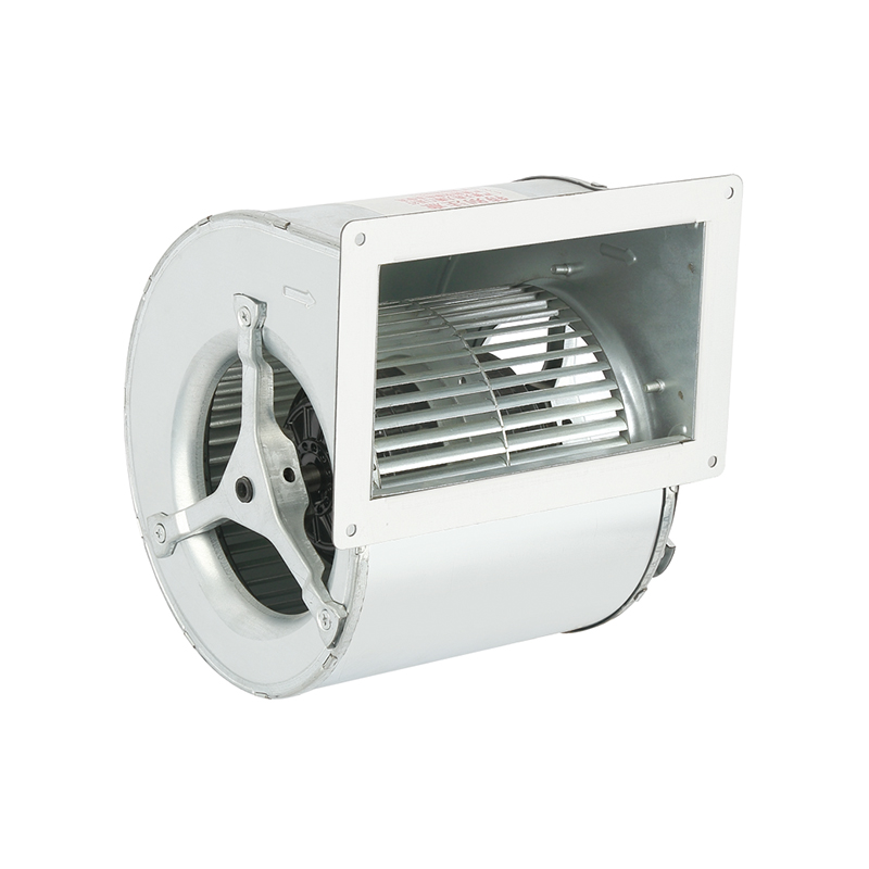
The DKT-160 Heat Dissipation Exhaust Double Inlet Air Conditioning Fan...
See Details
The DKT-180 Tilt Back Cool Down Double Inlet Air Conditioning Fan, a s...
See Details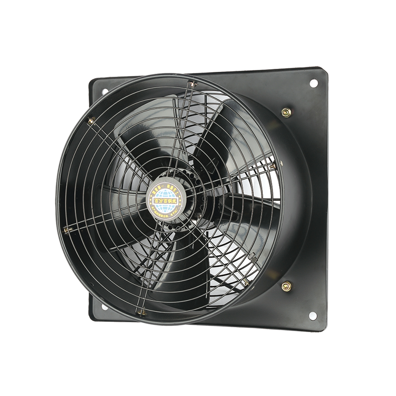
The YWF-400-2D2E Efficient Square form Axial fan is designed with a fo...
See Details
The YWF-350-2D2E Low noise Square form Axial Fan is designed with a co...
See Details
The YWF-350-4D4E Low vibration Square form Axial Fan is a outstanding ...
See Details
The YWF-400-4D4E Durable Square form Axial Fan is designed with advanc...
See Details
Qinlang focuses on providing high-quality products and considerate services, and is committed to meeting every expectation of our customers.
© Zhejiang Qinlang Electromechanical Co., Ltd.
Fans And Air-Cooling Equipment Factory
