 English
 русский
 عربى
عربى Español
Qinlang focuses on providing high-quality products and considerate services, and is committed to meeting every expectation of our customers.
The DKT-133 Cooling Ventilation Double Inlet Air Conditioning Fan is d...
See Details
An HVAC system uses energy in several places. Heating and cooling equipment draws attention because it handles the largest load. Fans receive less notice, yet they run whenever the system is operating, moving air through ductwork to every conditioned space. That continuous operation adds up over the course of a season.
The energy a fan consumes depends on two things: how much air it moves and how much resistance that air meets along the way. Ductwork introduces resistance through friction, bends, and fittings. Filters add more as they load with particles. Every point of resistance means the fan has to work harder to deliver the same airflow.
A High Efficiency Duct Fan addresses part of that equation. It moves air with less energy input for a given output, which reduces consumption across operating hours. The larger picture includes the ductwork, the controls, and how the system responds to changing demand. Each element influences the final result.
Understanding where savings come from means looking at airflow, fan design, and system operation together rather than treating any one factor in isolation.
Fan power does not rise in a straight line with airflow. As airflow increases, the power required to produce it rises at a steeper rate. Pushing more air through the same ductwork costs more than proportional energy, which is why oversizing a fan to handle a peak condition means paying for that capacity during every hour of operation.
Ductwork resistance plays a direct role in this relationship. Friction along duct walls, turbulence at bends and transitions, and pressure drop across filters all add to the load the fan must overcome. A system with higher resistance requires more energy to move the same volume of air.
Both too little and too much airflow carry penalties. Insufficient airflow leaves spaces under‑conditioned and can cause equipment to run longer than necessary. Excessive airflow wastes energy and can increase noise. The target is the airflow the system actually needs, delivered with as little resistance as possible.
Small changes in resistance can shift consumption in ways that accumulate. A filter that is partly loaded, a damper that is not fully open, or a duct section that has been compressed during installation each add resistance. Individually, the effect may be modest. Across a full system running for extended hours, the total becomes noticeable.
A fan's efficiency determines how much of the energy input becomes useful air movement rather than heat and noise. That efficiency, combined with the resistance of the system it serves, sets the energy cost of moving air through the building.
Several design elements contribute to lower energy use for the same airflow.
Motor design has a direct effect. Electronically commutated motors and permanent magnet designs convert electrical input into rotation with less loss than older induction motors. They also allow speed control across a wide range, which matters for matching output to demand.
Impeller geometry determines how air moves through the fan housing. Blade shape, angle, and spacing influence how smoothly air passes. A design that reduces turbulence inside the housing lowers the energy needed to produce a given airflow. The housing itself matters as well — a shape that guides air without abrupt changes reduces internal losses.
Variable speed operation allows the fan to run at the rate the system requires rather than at a fixed output. Since most systems operate below their peak demand for much of the time, the ability to reduce speed during part‑load conditions produces savings across those hours.
Bearing and drive losses are smaller contributors but still present. Reduced friction at the shaft and bearings means less energy diverted from moving air. Direct‑drive designs eliminate belt losses that appear in belt‑driven arrangements.
Airflow path within the unit affects how much resistance the fan works against. Smooth internal surfaces, gradual transitions, and adequate clearance around the impeller all reduce the energy required to move air through the housing.
Control integration determines whether the fan responds to actual conditions. A fan that runs at a fixed rate regardless of demand uses more energy than one that adjusts based on pressure, temperature, or occupancy signals. The controls connect the fan's operation to what the space actually needs.
| Design Element | Effect on Energy Use | Practical Consideration |
|---|---|---|
| Motor type | Lower conversion losses | Compatibility with existing controls |
| Impeller geometry | Reduced internal turbulence | Matched to airflow and pressure range |
| Variable speed | Output matches demand | Requires compatible control system |
| Bearings and drive | Lower friction losses | Maintenance access for service |
| Airflow path | Less internal resistance | Compact designs may add turns |
| Control integration | Avoids unnecessary operation | Sensor placement affects response |
A fixed‑speed fan runs at one output whenever it is on. If the system needs less air, the fan still delivers the same amount. The excess is either throttled by dampers — which adds resistance and wastes the energy already spent — or allowed into the space, where it may cause over‑conditioning.
Variable speed changes that behavior. The fan adjusts its output to match what the system requires at any given moment. During periods of low demand, it runs slower. During peak conditions, it speeds up. The energy consumed follows the actual need rather than a fixed assumption.
Lower speeds reduce power draw at a rate that exceeds the reduction in airflow. Running a fan at a reduced speed to deliver part of its capacity consumes less energy than running at full speed and throttling the output. The difference accumulates across the hours a system spends at part load.
Part‑load conditions dominate in most buildings. Design capacity is sized for the hottest or coldest conditions, which occur for a limited portion of the year. The rest of the time, the system operates below that peak. A fan that can reduce output during those hours uses less energy than one that cannot.
Controls make variable speed practical. Pressure sensors in the ductwork, temperature sensors in conditioned spaces, or occupancy signals can all inform the fan's operation. The control strategy determines how closely the fan's output tracks actual demand. A well‑matched strategy keeps the fan operating near the point where it uses the least energy for the airflow required.
The combination of an efficient motor and variable speed control produces savings that neither element delivers alone. The motor reduces losses at any speed, and the control ensures the fan operates at the speed the system needs rather than at a fixed rate.
Fan efficiency addresses one side of the energy equation. The other side is the resistance the air meets as it travels through the system.
Duct sizing sets the baseline. A duct that is too small forces air to move at higher velocity, which increases friction and pressure loss. A duct that is larger than needed reduces velocity but adds material cost and may not fit within available space. Sizing that matches airflow requirements keeps velocity within a range where friction stays manageable.
Bends, transitions, and fittings are common sources of pressure loss. Each turn in the duct path adds resistance. Gradual transitions and long‑radius bends create less turbulence than sharp corners and abrupt changes in cross‑section. Routing that minimizes the number of turns reduces the load on the fan.
Flexible duct performs differently from rigid duct. The corrugated surface creates more friction than a smooth interior, and the effect increases when the duct is compressed or routed with tight bends. Where flexible duct is necessary for connection, keeping runs short and straight preserves airflow. Long runs of flexible duct in place of rigid duct add resistance that the fan must overcome.
Sealing leaks prevents conditioned air from escaping before it reaches the intended space. Leaks at joints, connections, and access panels allow air to escape into unconditioned areas such as attics or wall cavities. The fan still moves the air, but the benefit does not reach the space it was meant to serve. Sealing these points reduces the volume the fan must move to achieve the same result.
Routing that shortens runs reduces both friction and the number of fittings. A system designed with the fan located close to the areas it serves uses less energy than one where air travels a long distance through multiple branches.
Fan efficiency and duct design interact. A more efficient fan reduces the energy needed for a given airflow, but high resistance in the ductwork can offset those gains. Addressing both together produces better results than focusing on either alone.
Savings from efficient fans and reduced resistance show up in specific types of systems and operating patterns.
Continuous operation areas are where part‑load performance matters. A system that runs for long hours spends much of that time below design capacity. The ability to reduce output during those periods produces savings across the operating season.
Systems running below design capacity for much of the time are common in buildings where the design was sized for peak conditions that occur infrequently. The fan operates at a fraction of its capacity for the majority of hours. Variable speed control in those situations reduces consumption compared with fixed‑speed operation.
Zones with varying occupancy or process demand benefit from controls that respond to actual conditions. A space that is heavily used during part of the day and lightly used at other times does not need the same airflow throughout. Adjusting output to match occupancy reduces energy use during low‑demand periods.
Retrofits of existing fixed‑speed fans offer opportunities where the original equipment runs at one rate regardless of demand. Replacing a fixed‑speed motor with a variable‑speed alternative and adding controls allows the system to match output to conditions. The ductwork may also need review, since existing systems sometimes carry resistance that was not addressed when installed.
Buildings where ductwork has not been reviewed often have opportunities that are separate from fan efficiency. Leaks at joints, compressed flexible duct, and filters that are not changed on schedule all add resistance. Addressing these issues improves the performance of any fan, whether or not it is replaced.
Applications with long operating hours see the cumulative effect of efficiency improvements. A system that runs continuously for a season uses enough energy that even modest reductions in consumption produce measurable savings. Systems that operate intermittently have less opportunity for the same level of savings.
Savings vary across installations. Several factors determine how much of the potential benefit appears in practice.
These factors do not act independently. A fan with an efficient motor and variable speed control still consumes more energy than necessary if the ductwork leaks or the filters are loaded. Conversely, a well‑sealed duct system with low resistance allows an efficient fan to deliver its full benefit.
The load profile deserves particular attention. A system that operates at or near full capacity for most of its running hours has less opportunity to benefit from variable speed operation than one that spends most of its time at part load. Reviewing how the system actually operates — rather than how it was designed to operate — provides a clearer picture of where savings are available.
A few practical steps help translate efficient equipment into lower consumption.
Monitoring deserves emphasis. Without measurement, it is difficult to know whether a change produced the intended effect. Tracking energy use before and after an adjustment provides feedback that guides further decisions.
Maintenance practices also influence performance over time. A system that is commissioned well but not maintained will gradually lose efficiency as filters load, belts wear, and components drift from their settings. Regular attention keeps performance closer to the level it had when installed.
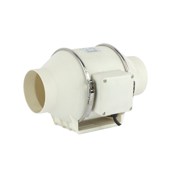
A High Efficiency Duct Fan reduces the energy required to move air through a system. That reduction comes from motor design, impeller geometry, and the ability to adjust output to match demand. Variable speed operation allows the fan to run below full capacity when conditions allow, which is where much of the savings appear across a season.
Fan efficiency is one part of the picture. Ductwork resistance, leakage, and filter condition all influence how much energy the system consumes for a given airflow. Addressing these factors alongside equipment selection produces better results than focusing on any single element.
Actual savings depend on how the system operates. Hours of use, load profile, existing equipment condition, and control strategy all shape the outcome. Systems that run for long periods at part load have the clearest opportunity to benefit.
Treating airflow as a system rather than a collection of separate components keeps the focus on where energy is actually used. Efficient equipment, well‑designed ductwork, and controls that respond to real conditions work together to reduce consumption. The result is a system that delivers the airflow the space requires with less energy spent producing it.
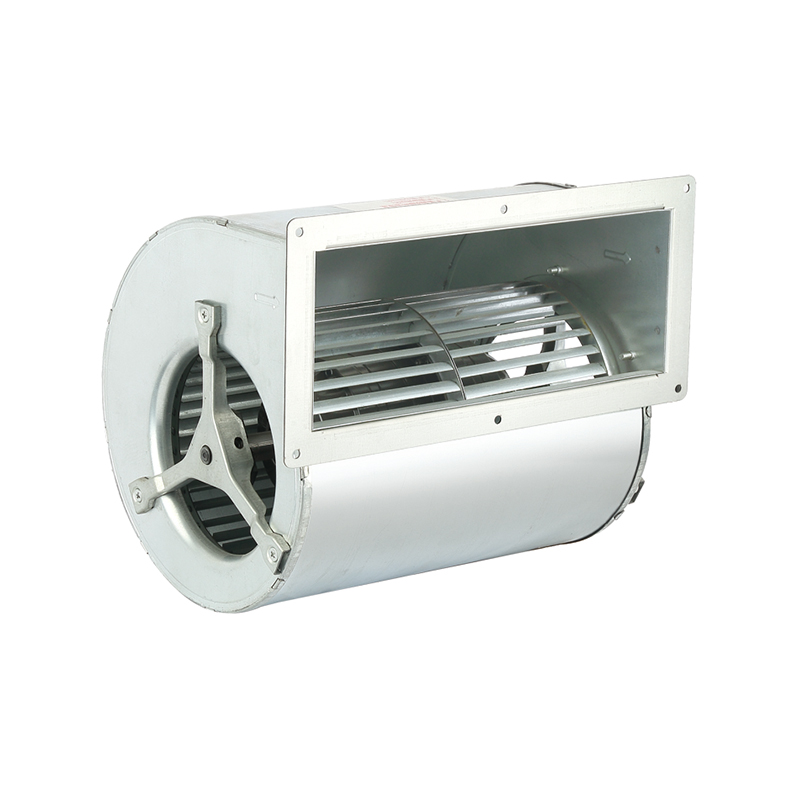
The DKT-133 Cooling Ventilation Double Inlet Air Conditioning Fan is d...
See Details
The DKT-146 Multi-Function Variable Frequency Double Inlet Air Conditi...
See Details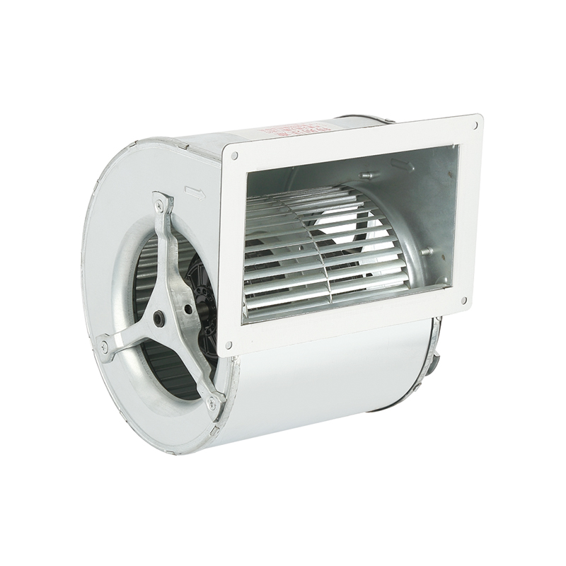
The DKT-160 Heat Dissipation Exhaust Double Inlet Air Conditioning Fan...
See Details
The DKT-180 Tilt Back Cool Down Double Inlet Air Conditioning Fan, a s...
See Details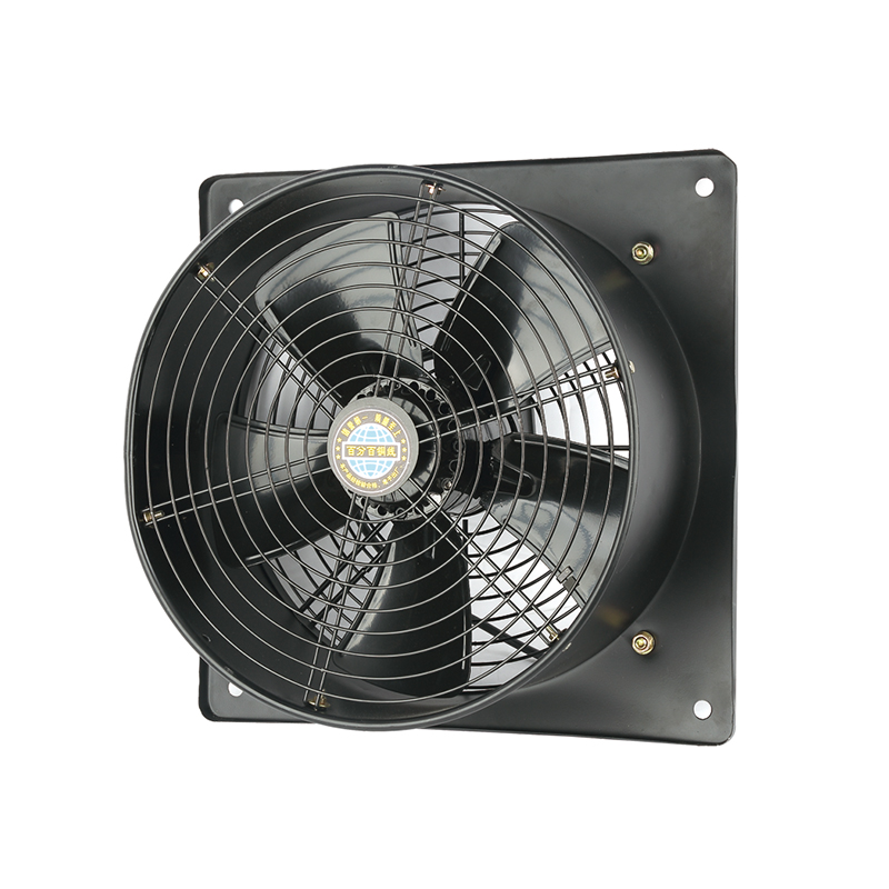
The YWF-400-2D2E Efficient Square form Axial fan is designed with a fo...
See Details
The YWF-350-2D2E Low noise Square form Axial Fan is designed with a co...
See Details
The YWF-350-4D4E Low vibration Square form Axial Fan is a outstanding ...
See Details
The YWF-400-4D4E Durable Square form Axial Fan is designed with advanc...
See Details
Qinlang focuses on providing high-quality products and considerate services, and is committed to meeting every expectation of our customers.
© Zhejiang Qinlang Electromechanical Co., Ltd.
Fans And Air-Cooling Equipment Factory
